Multicast reminds me of cells. One cell duplicate into more cells, and even more down the chain. These cells could carry the good stuff or the bad stuff. In this article, we will explore more how multicast can deliver all the good stuff to support MP-BGP EVPN VXLAN, to create an efficient underlay.
In the previous post, Baby Steps with MP-BGP EVPN VXLAN, we have created a simple L2 overlay service, operating across a L3 underlay. The underlay consist of OSPF for routing between VTEPs and Protocol Independent Multicast Sparse-Mode (PIM-SM) for handling Broadcast, Unknown Unicast and Multicast (BUM) traffic. Before we jump into Distributed Anycast Gateway (DAG) or configuring L3 overlay, we need to turn back the pages to revisit the topic of underlay multicast and the way BUM traffic is handled.
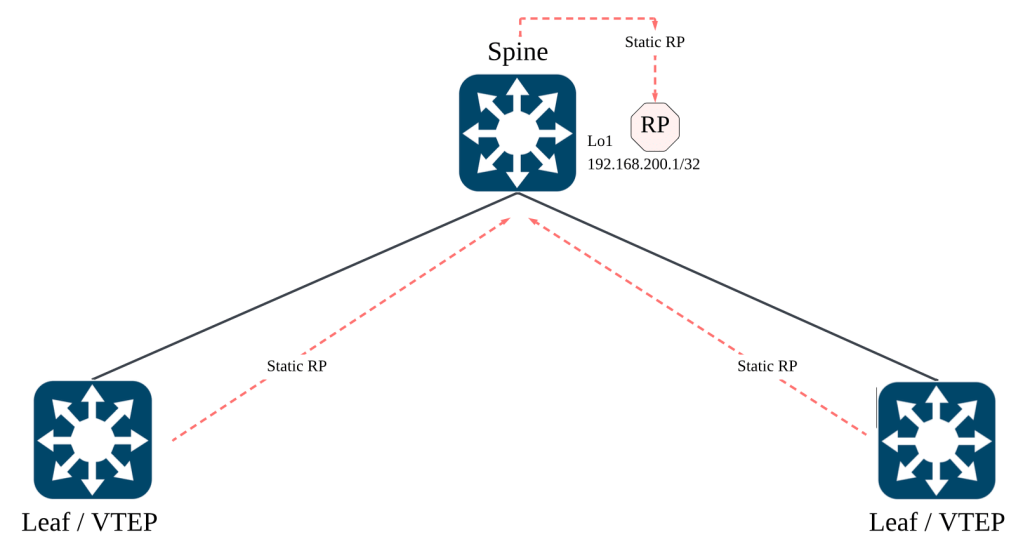
Going back to the earlier diagram on underlay multicast, the Rendezvous Point (RP) is typically located on the spine switch. The leaf switches in our lab environment will configure the static RP to the loopback 1 (192.168.200.1/32) interface.
Finding Comfort In Basics
Now, most of us might find the concept of multicast daunting. I think it is true and it is still daunting to me till this day. But every high technology relies on solid fundamentals. Whenever we feel stuck, we just need to find comfort that we have yet to get to the bottom of the stack. Find the bottom, reach the source, and start from there.
Before we dig in, some foundation knowledge on Protocol Independent Multicast (PIM) is advisable, especially on PIM-SM operation. While the aim of this article is not to deep dive into PIM-SM, the concepts of Rendezvous Point (RP), (S, G) and (*, G) will be briefly discussed.
Every VTEP is a Source and Receiver of Multicast
In vanilla multicast, the typical use case is to have a sender transmitting to multiple interested receivers in a particular direction. The sender will likely always be the sender and the receiver will likely always be a receiver in a given multicast group.
In MP-BGP EVPN VXLAN, the underlay uses multicast to handle BUM traffic such as Address Resolution Protocol (ARP). As protocols such as ARP may be sourced from any hosts connected to any leaf switches, this means that every leaf can act as both a sender and receiver of multicast traffic for a specific group.

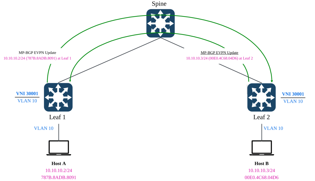
From the previous post, Baby Steps with MP-BGP EVPN VXLAN, we have associated the L2 VNI of 30001 to the multicast group 255.0.0.101. This means that any BUM traffic for L2VNI 30001 originating from any participating leaf switches, will be sent to the multicast group 255.0.0.101 in order to reach all other leaf switches.

In above example, if host A that is connected to leaf 1 initiates an ARP, leaf 1 will multicast the traffic to 255.0.0.101. Leaf 2 will receives the traffic because the switch is also a receiver of the multicast group 255.0.0.101.
Vice versa, if host B that is connected to leaf 2 initiates an ARP, leaf 2 will multicast the traffic to 255.0.0.101. Leaf 1 will receive the traffic because the switch is also a receiver of the multicast group 255.0.0.101
This is an important concept to understand when we go into the weeds of interpreting the multicast verification outputs.
Interpreting (*, G) and (S, G)
In the world of PIM-SM, we often use the (S, G) and (*, G) notation. In some documentation, we see that (*, G) refers to any source sending multicast traffic to a specific multicast group (E.G 225.0.0.101). (S, G) refer to a specific source sending multicast traffic to a specific multicast group (E.G 225.0.0.101).
To help you not fall into the same understanding pitfall as I once did, the (S, G) and (*, G) does not necessarily mean that the S and * refers to actual multicast senders. It could also meant the PIM Join messages.
Initially when the Network Virtualization Edge (NVE) is up, each leaf will send a PIM-Join message to the RP with the intent to join the multicast group 225.0.0.101. The multicast group, 255.0.0.101, was defined in the NVE configuration section where the L2VNI 30001 is mapped to the specific multicast group.

The PIM-Join message signals to the RP with the intent from the local leaf to receive multicast traffic from the group 255.0.0.101 if there are any of such traffic. For example, if the remote leaf switch receives any BUM traffic from its connected host, it will be sent via underlay multicast towards the spine, and the local leaf switch will receive such traffic because it has joined the multicast group.
The Star Comma Gee (*, G)

From the multicast routing table (mroute) of each leaf switch, we will observe the (*,G) entry whereby the G refers to the multicast group 225.0.0.101. This is a PIM Join message sent from the local leaf’s RP facing interface, towards to RP. This is to signal the intent to receive any messages pertaining to the multicast group 225.0.0.101.

To test out the theory, we can run a packet capture on the spine’s interface, facing towards leaf 1. We could also do a packet capture on the spine’s interface, facing towards leaf 2, but it will yield the same result. The objective is to capture the PIM-Join message received from the leaf switches.

From the packet capture, we can use Wireshark to filter specifically to “Join/Prune” to identify PIM-Join messages. You might notice that the source is “192.168.100.2” and the destination is “224.0.0.13”. The source is the RP-facing interface of leaf 1 as it sends the PIM-join messages toward the RP. The destination “224.0.0.13” is a well-known multicast group address for all PIM-capable routers. In this case, the spine will be able to receive this PIM-Join message as it is PIM-capable.

The packet capture shows that leaf 1 has sent a PIM-Join towards the RP, which is reachable via 192.168.100.1. We can observe similar behaviour in leaf 2 as well so there is no need to replicate the test scenario.
The Ess Comma Gee (S, G)
Once all the respective leaf switches has indicated their intent to receive multicast traffic for the multicast group (225.0.0.101) associated with L2 VNI 30001, they will wait for such packets patiently.
When host A comes up and it wants to trigger an ARP or send any broadcast, this is where the underlay multicast will be leveraged. Revisiting the concept of PIM-SM and the RP. The RP exist as a meet-up point between the senders and the receivers so that there is no need to resort to flood and prune as per PIM dense mode. Once the RP manage to connect the multicast traffic between the sender and receiver, the receiver will send a PIM-Join directly towards the sender, effectively finding the best path towards the source.
In our case of a spine-leaf topology, the best path is still through the spine where the RP is located. But with this, the multicast routing table of each leaf will create a more specific (S, G) entry where the S specifies the exact source for G, the multicast group. This step is part of the native operations in PIM-SM, but in our current scenario, there will be no change in terms of the path taken for underlay multicast traffic.

Using leaf 1 as an example, after the connected hosts in both leaf starts to send BUM traffic, we can notice two additional (S,G) entries on the multicast routing table.
If you recall, we have discussed that in MP-BGP EVPN VXLAN, every VTEP is both a sender and a receiver of a multicast group. Hence we should be able to expect that every VTEP is also an Source (S) in the (S, G) notation.
The first entry highlighted in yellow, shows that the VTEP of leaf 2, using its loopback 0 (192.168.200.3), is a source for multicast group 255.0.0.101. The incoming interface where traffic will be received is via its RP-facing interface, towards the spine.
Vice versa for the second entry highlighted in turquoise, it shows that the VTEP of leaf 1, using its loopback 0 (192.168.200.2) is also a source for multicast group 225.0.0.101. The incoming interface is its own loopback because the VTEP will receive BUM traffic and convert them into underlay multicast.
Why is Tunnel 0 an Outgoing Interface?

I have also asked myself the same question and got mind boggled for a while, trying to comprehend what is happening. Tunnel 0 is being used as the VXLAN tunnel and Loopback 0 is being used by the VTEP. How does underlay multicast get involved with the overlay technology? To understand further, one way is to jump straight in and observe the packet capture.
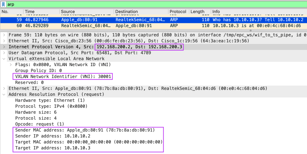
Using the earlier packet capture, we can zoom into one of the ARP request initiated by host A, connected to leaf 1. It is trying to ARP to its configured default gateway, 10.10.10.1. It will not receive a reply because the default gateway does not exist yet in our environment. However, what matters is the how the packet is structured.

We can observe an interesting point. The BUM traffic, in this case ARP, is first being VXLAN encapsulated, before being sent out on the underlay to the multicast group 225.0.0.101, sourced by the VTEP.

The packet capture shows that the inner workings of underlay multicast in the context of MP-BGP VXLAN EVPN. BUM traffic from the directly connected host will hit the VTEP first and be VXLAN encapsulated with the correct VNI. Only after the BUM traffic is VXLAN encapsulated, then the BUM traffic will be sent out as multicast towards other interested receivers for the group 225.0.0.101.
This will make sense when we apply the (S, G) concept to our understanding. The S will be the leaf 1’s VTEP, and the group is 225.0.0.101. The incoming interface is Loopback 0 (VTEP), because the BUM traffic must be first VXLAN encapsulated before going out on multicast. The destination interface is the spine-facing interface, to be sent to other leaf switches.

On leaf 2, the incoming interface is the spine-facing interface where the BUM traffic from leaf 1 has been multicast-ed through the spine and towards itself. The outgoing interface is set as Tunnel 0 because we need to remember that the multicast traffic was previously being VXLAN encapsulated first. Once the multicast traffic reaches its destination, we need the VTEP to decapsulate the traffic so that the underlying BUM traffic can reach its destination.
ARP Suppression
When host A’s MAC/IP address is learnt locally on a switch, the MP-BGP EVPN control plane protocol will advertise these information, along with the connected VTEP as next-hop to the fabric. On the remote leaf switches, if there are remote endpoints that wishes to talk to host A, it will sends out an ARP towards the remote leaf switch. However, because the remote leaf switch already understand via the MP-BGP EVPN control plane the IP/MAC of host A and its location, it does not need to flood the ARP traffic out via multicast.
The idea is to reduce traffic overhead in the fabric. While multicast alone is significantly better than the typical flood and learn mechanism of ARP, it will still consume substantial bandwidth when applied at scale. Hence, the handling of BUM traffic using multicast should be conserved for the actual unknown destination. ARP suppression is handled differently in NX-OS (Nexus 9000) and IOS-XE (Catalyst 9000).
ARP Suppression on NX-OS (Nexus 9000)
On NX-OS, ARP suppression is handled in the form of the leaf switches providing the ARP response back to the requesting host. In such a mechanism, if the MAC/IP is already known by the local leaf switch via the MP-BGP EVPN update, the ARP request will never be sent via multicast to other participating leaf switches for a specific VNI.
ARP Suppression on IOS-XE (Catalyst 9000)
For IOS-XE, even if the IP/MAC of the remote host is known by the local switch, the local leaf switch will not provide the ARP response back to the requesting host. Instead, the local leaf switch will trigger a ARP request unicast towards the remote leaf switch that is connected to the remote host. Unicast is possible because via the MP-BGP EVPN update, the local leaf switch knows that for the IP/MAC binding, it is reachable via leaf 2 (for example).
Since our lab is using Catalyst 9300 switches, we will dive into observing the behaviour of ARP suppression on IOS-XE.

By default, ARP suppression has been enabled by the MP-BGP EVPN VXLAN Fabric. We can do a packet capture to observe the behaviour of ARP being unicast-ed to the remote leaf.

In our lab example, we will connect both host A and host B to their respective leaf switches and have them attempt to ping each other. Prior to being able to send an ICMP echo, both hosts will need to resolve MAC address of each other via ARP. We will be performing a packet capture on the spine switch to observe the ARP packet exchange between the hosts.
Looking at ARP request from host A to host B, we can validate that the ARP request are indeed being unicast-ed from leaf 1 to leaf 2 over VXLAN on L2VNI 30001. The fabric unicast directly to the leaf switch that has host 2 connected on its ports because via MP-BGP EVPN control plane, it knows.
With the exception of known IP/MAC host, the other remaining BUM traffic will take the regular underlay multicast to reach its required destination.
Summary
I hope you have enjoyed this article as much as I have enjoyed learning and penning down my thoughts. We have observed how multicast can be applied in various way, to be part of the cogwheel to support the overall MP-BGP EVPN VXLAN operations.
With this, we are ready to venture into L3VNI, to dig into how inter-subnet traffic can be managed. Till next time!
Tang Sing Yuen, Cisco Solutions Engineer

Leave a comment