• In today’s example, we will be demonstrating routing between host A and host B in different subnets, but within the same tenant (VRF). While routing in traditional networking is built into the DNA of network engineers, when working with overlay technologies, routing adds an interesting twist to challenge our understanding.

    Opening Thoughts

    My learning journey on MP-BGP EVPN VXLAN has been interesting to say the least. I’ve always used multiple materials to learn the same topic because there will be different perspective and coverage angle depending on the author. For MP-BGP EVPN VXLAN, I have used Cisco Live, Cisco press books and even configuration guides to learn. Especially for L3 overlay technologies, I have found the use of certain networking constructs confusing, such as the need to use VRF or BGP IPv4 address family, and how does it apply to our use case. I hope you will find this piece as entertaining as I have found exploring and writing the foundations of L3VNI and the supporting technologies to enable L3 overlay service.

    Technically, we could configure an L3 overlay service on MP-BGP EVPN VXLAN without really understanding why certain configuration is required or how they support the entire solution. But this is not what we should do here. As much as we can, we should be responsible for every line of configuration, and understand how they fit in to the use case.

    Let’s lab and learn together.

    Major Questions

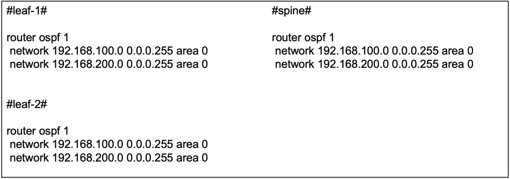
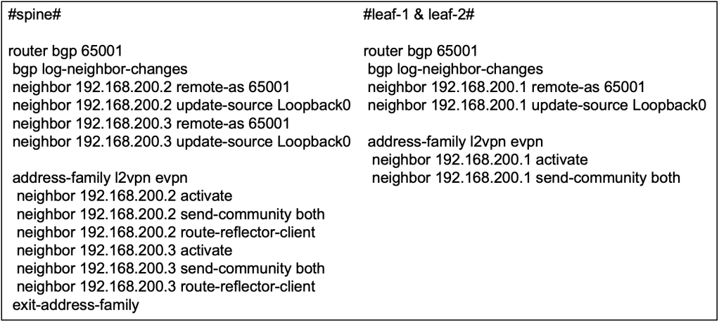
    In my journey to explore L3 overlay using MP-BGP EVPN VXLAN, I found myself asking for the purpose of certain protocols that are used as building blocks for the entire solution. Referencing to Cisco Live BRKENS-3840 (Under the Hood of IOS-XE EVPN/VXLAN on Catalyst 9000) by Dmytro Vishchuk, he has brilliantly came up with a sample config, shown below.

    Apart from the obvious that we need an L3VNI, associating the L3VNI to the NVE, I have found myself asking these questions, to myself.

    1. Why is VRF required if I do not have multiple L3VNI / L3 Overlay service?
    2. What is BGP IPv4 address family required when we already have EVPN address-family?
    3. Why do we need route target? What is stitching?

    If you may have similar questions like I do, perhaps this blog post will be relevant to you.

    Similarity to MPLS L3 VPN

    I personally find the foundation of MPLS L3 VPN to be similar in concept to L3 overlay in MP-BGP EVPN VXLAN. The diagram below is an example of the topology of MPLS.

    The MPLS network is similar to MP-BGP EVPN VXLAN because it is also meant to support multiple L3VNI or L3 overlay service, multi-tenancy in short. The MPLS Provider (P) routers that perform label switching is similar to the VXLAN underlay that routes traffic between VTEPs based on the outer IP headers. The MPLS Provider Edge (PE) routers are similar to the VTEPs such that they participate in MP-BGP control plane and they are responsible for interfacing between the underlay and the consumers. The MPLS Customer Edge (CE) are similar to the consumers (a.k.a host) as they need to be isolated from other organization.

    The MPLS network that is a shared medium that will be used by multiple independent organisations to route traffic between each other. For scalability, the MPLS network will use a single BGP instance to exchange prefixes between sites. Route Distinguisher (RD) will be used to ensure IP addresses are non-overlapping. MP-BGP VPNv4 will be used to exchange the prefixes between PE routers. Route Targets (RT) will be used to ensure that the PE import and export to organisation VRF, only the prefixes that belongs to a that organisation.

    With the above understanding, we will find that MP-BGP EVPN VXLAN employs similar concept, and more.

    Purpose of VRF in EVPN Fabric for L3 Overlay

    To understand how routing works in a MP-BGP EVPN VXLAN, we need to first understand the purpose of Virtual Routing and Forwarding (VRF) in the fabric. The next generation data center fabric is built with multi-tenancy in mind. The data center could be serving multiple customers, or their sub-organization could require isolation between their workloads and traffic. VRF is used in the networking infrastructure to support segmentation at a macro level.

    Why is VRF Configuration Required for Intra-VRF Communication?

    Well, the short-answer I believe is the use of overlay technologies. As the next-gen data center and MP-BGP EVPN is designed with multi-tenancy in mind, even for a lab environment with only 1 tenant (a.k.a 1 VRF), the configuration still need to include 1 VRF. Not forgetting that there is an underlay in a the fabric as what we have discussed in previous blog post. The separation of overlay (VRF) and underlay (GRT) routes further necessitates the presence of VRF even when there is only 1 tenant.

    Why is EVPN Insufficient as Control Plane for Routing?

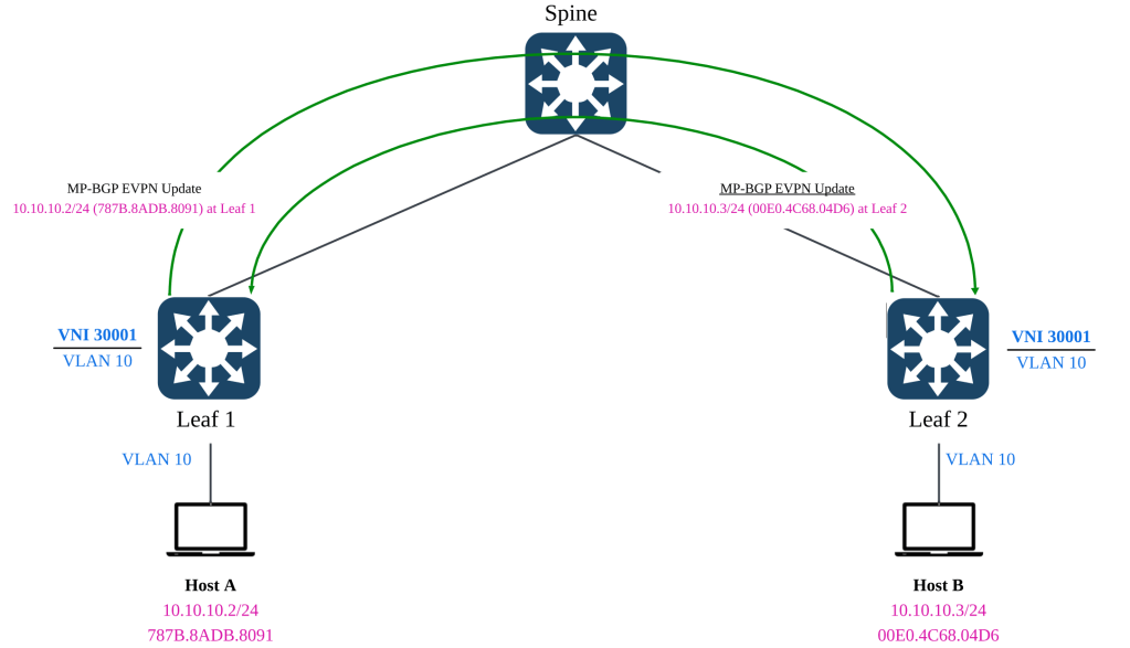
    In the previous blog post in which we have discussed bridging using L2VNI, we have leveraged on MP-BGP EVPN address family. With EVPN supporting optional IP prefixes, VTEPs in the fabric are able to learn the MAC and IP bindings of the hosts, and the remote VTEPs that its located.

    For routing between different L2VNIs or subnets, we will not able to rely solely on EVPN. Although, EVPN can carry both MAC address, MAC address with IPv4 address and IPv4 subnet routes (Type-5), this is insufficient from a routing standpoint.

    Routing Policy & Control

    In layer 3 routing, there will be instances whereby injecting a default route to external gateway is required, or to control the leaking of routes between VRFs via route import & exports and manipulation of next hops via Policy Based Routing (PBR). These capabilities are not support by the limited optional L3 attributes in EVPN. Furthermore, since the L3 attributes (E.G Type 5 network routes) is optional, routing cannot depend on it being optional.

    Support for Multi-Tenancy

    As mentioned earlier, the use of VRF even for a single L3VNI is required because the solution is built with multi-tenancy in mind. The presence of overlay and underlay signals the need for routing separation between underlay (GRT) and overlay (VRF). With multiple L3VNI (VRF) in play, the MP-BGP control plane must be capable of advertising the host and network routes in isolation from the other L3VNIs (VRF).

    Although EVPN is able to carry the L3VNI tag in its advertisement, EVPN is not able to support key L3 capabilities such as prefix exchange, route leaking and external connectivity with multi-tenancy (VRFs) in mind. The L3VNI tag in EVPN advertisement is only to signal which VNI to be used for routing when bridging is insufficient.

    Lab of the Day (LOOD)

    In the lab work today, we will be setting up routing between host A and host B that resides in different L2VNI, but within the same L3VNI. In layman terms, this will be inter-subnet routing in the same VRF.

    Both leaf 1 and leaf 2 will be configured with the Distributed Anycast Gateway (DAG) to support Layer 3 routing. Essentially the end goal is to allow both hosts to have reachability to each other using the L3VNI. As this scenario is not designed to test the mobility of the host, we will not be aligning the MAC address of the default gateways yet.

    L2VNI Preparation

    Before we proceed with the most interesting part of today’s topic, we must make sure that we have the L2VNIs setup in both switches. Technically, we only require one unique L2VNI per switch but since we continuing on from previous lab, we already have L2VNI 30001 configured on both switches in the previous article. We shall proceed to configure L2VNI 30002 on both switches as well.

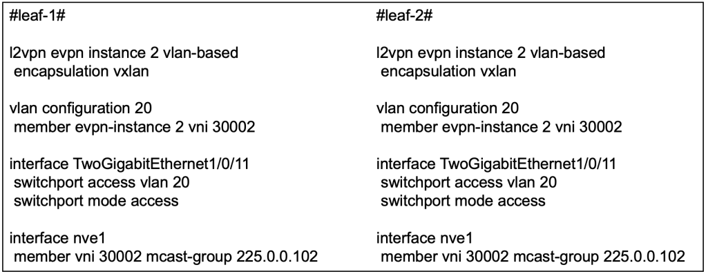
    At this point, if host A and host B are connected to Tw1/0/11, they will be able to reach each other using L2VNI 30002.

    L3VNI Preparation

    VRF Definition

    The first activity we need to do is to create a new VRF to represent the L3 overlay service, L3VNI. In this example, we will use VRF red.

    We have also defined the Route Distinguisher (RD) to be used in conjuncture with the VRF. RD unlike route target, has a subtle use case. In a multi-VRF environment where overlapping IP addresses may occur, RD provides unique-ness to the address. Hence, both leaf can use the same RD for the same VRF because they will not have overlapping IP address.

    In subsequent articles where we dive into multi-tenancy or access to shared services, we will revisit this sub-topic and each VRF will require their own distinct RD.

    L3VNI Definition

    Next, we will create a new VLAN to associate to a L3VNI.

    In this example, we will create a dummy VLAN 500 and associate it L3VNI 50001. With this config alone, there is still no indication that the VNI is L3.

    We will then create an SVI for the VLAN 500. This SVI will have no IP address and will be assigned the VRF (red) to be used. Essentially, this SVI will be used for routing between the VTEPs.

    The command no autostate is required because there will not be any access or trunk ports associated with this SVI. Without the command, this interface will go down.

    Distributed Anycast Gateway (DAG)

    Now let’s move into the section on configuring the default gateway for L2VNI 30001 and L2VNI 30002. Because the lab is on routing between subnets / L2VNIs, we will need to provide default gateways for the subnets.

    In both leaf, because we are using DAG, the IP address on both SVI will be the same. We will also put them in the same VRF (red) so that routing between the subnets will traverse over the same L3 overlay (L3VNI).

    Because in the current lab scenario, we are testing routing between hosts on different subnet, we do not require to configure the same default gateway MAC address on the VTEPs. We will need to configure the same default-gateway MAC address on the VTEPs when we test endpoint mobility between the leaf switches. We will leave that for the later section. So at this point, this is still not fully a DAG yet.

    Enabling L3VNI on NVE

    On the Network Virtualization Edge (NVE), apart from the existing L2VNI association, we will need to associate the L3VNI with the VRF.

    MP-BGP IPv4 Unicast for L3 Overlay Control Plane

    As discussed in the initial section, we will require the use of IPv4 unicast address-family in BGP to advertise L3 reachability in the fabric because EVPN is mainly used for L2 bridging. In this section, we will be configuring the additional IPv4 unicast address family in the MP-BGP.

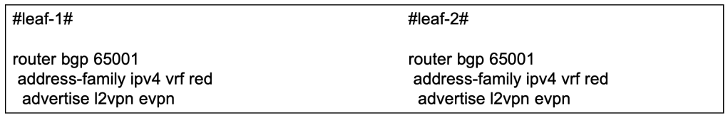
    The reachability information is originally sourced from the EVPN protocol, hence we will need to advertise the EVPN information into the BGP IPv4 address family to be used in L3.

    Route Target Import & Export

    In the context of multi-tenancy where multiple L3VNI will exist, the VTEP which will be shared among the L3VNIs will need a way to isolate the routes received from BGP. Apart from isolating the routes, we may also need some mechanism to leak the routes between VRFs at the VTEP. We can do so using Route Targets.

    In our configuration above, you might find that both leaf-1 and leaf-2 are both importing and exporting the same RT via the VRF IPv4 address family. This is only the case when we only have a single overlay VRF.

    Both VTEP are configured to export its prefixes with the RT of 10:10, and to receive prefixes with the RT of 10:10. This means that the prefixes exported by both VTEP, for VRF red, will all be received by the opposing VTEP. We’re trying to make a simple topology here, hence no fuss on the import and export route targets.

    However, you might notice that there is a key word “stitching” on import and exports. Why is that so? Let’s move on to the next section.

    Stitching RTs for L2VNI and L3VNI

    We may often forget that L3VNI and L2VNI have their own respective route targets. Earlier, we have configured to import the VRF to import routes based on RT 10:10. The RT 10:10 was exported under address-family IPv4. However, the EVPN prefixes are not configured with RT 10:10, hence they are not imported yet.

    In our example, we have not configured the RT for our L2VNI (30001) and L2VNI (30002). Hence they will use the default format of ASN:EVI, hence it will be 65001:1 and 65001:2.

    This is important because when we advertise L2VPN EVPN via the BGP IPv4 unicast address-family for VRF (red), the BGP protocol is taking the learnings from the EVPN and into the IPv4 unicast address-family. Assuming the EVPN information, now riding on IPv4 unicast address-family reaches the destination VTEP, it is up to the VTEP to decide if it will import the prefixes. Hence, this means that the VRF definition on the VTEP needs to import the RT of the L2VNIs that are part of the L3VNI (VRF).

    Without importing the EVPN prefixes from the L2VNIs, we will not be able to support inter-subnet, intra-VRF routing because our local VTEP will not be able to learn which hosts or which subnet are residing behind which remote VTEPs.

    In NX-OS configuration, we can configure specifically which L2VNI RT to import for a specific VRF. However, for IOS-XE, there is no such command. Instead, stitching is used to import all related L2VNI’s RT within a specific L3VNI.

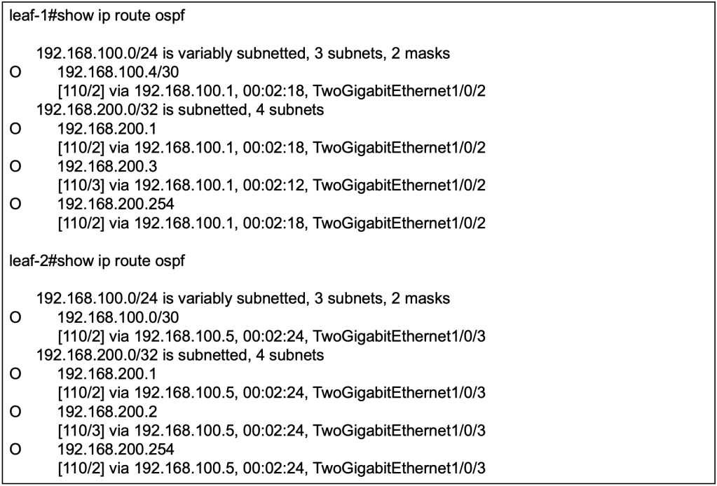
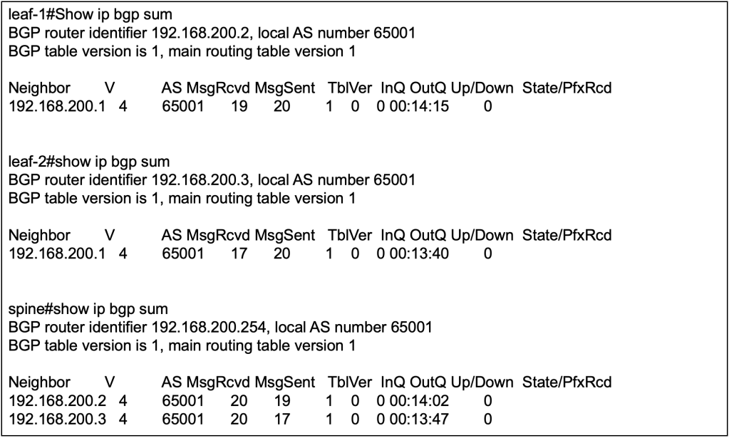
    Verification of MP-BGP & RIB

    Show ip bgp l2vpn evpn detail

    Leaf 1’s BGP EVPN has learnt the IP & MAC binding of the host B behind leaf 2.

    By reviewing the detailed output of the BGP L2VPN EVPN, we can observe that the type-2 EVPN prefixes contain the L2VNI & L3VNI and the RT of the L2VNI & L3VNI. The BGP’s IPv4 unicast address family will advertise the EVPN prefixes into its unicast address-family updates.

    When the BGP updates reaches the VTEPs, the leaf switches will need to decide which of the L2 (EVPN) and L3 (unicast) information to import to its VRF. This is where the RT of L2VNI and L3VNI is important because over at the VRF definition, we will configure which RT to import for unicast prefixes, and to stitch all the EVPN prefixes from all L2VNI associated to the L3VNI (VRF).

    show ip route vrf red

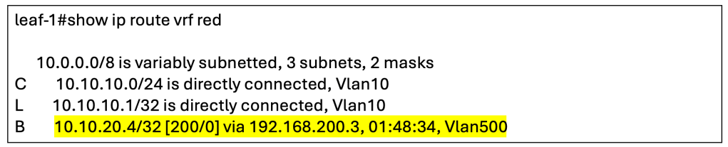
    The output has shown that the host route for host B has been installed into the RIB.

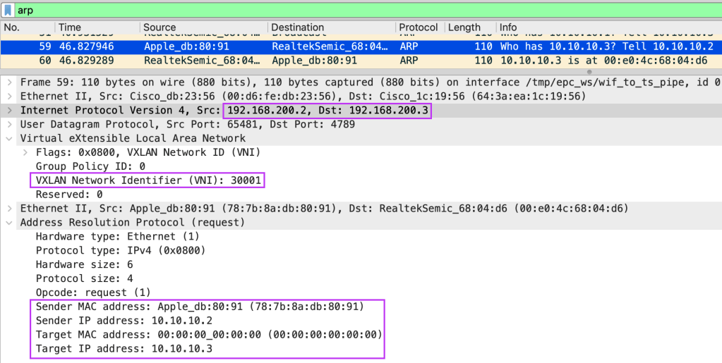
    Wireshark Verification

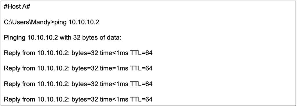
    We will now initiate a ping from host A (10.10.10.2/24) to host B (10.10.20.4/24).

    We will perform a packet capture on the spine switch to observe the ICMP echo request coming from host A.

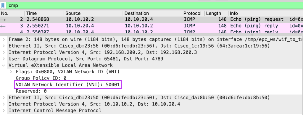
    From Wireshark, we can observe that the ICMP echo request between different subnets will use the L3VNI (50001) as both host A and host B are still in the same L3VNI, VRF.

    Closing Thoughts

    This has been a really long topic to learn and write. For sure we have only breach the surface on L3 overlays, but we had a pretty good run in exploring the technology. I hope you have like the articles thus far, next-up we will venture into external connectivity.

    Tang Sing Yuen, Cisco Solutions Engineer

  • Multicast reminds me of cells. One cell duplicate into more cells, and even more down the chain. These cells could carry the good stuff or the bad stuff. In this article, we will explore more how multicast can deliver all the good stuff to support MP-BGP EVPN VXLAN, to create an efficient underlay.

    In the previous post, Baby Steps with MP-BGP EVPN VXLAN, we have created a simple L2 overlay service, operating across a L3 underlay. The underlay consist of OSPF for routing between VTEPs and Protocol Independent Multicast Sparse-Mode (PIM-SM) for handling Broadcast, Unknown Unicast and Multicast (BUM) traffic. Before we jump into Distributed Anycast Gateway (DAG) or configuring L3 overlay, we need to turn back the pages to revisit the topic of underlay multicast and the way BUM traffic is handled.

    Going back to the earlier diagram on underlay multicast, the Rendezvous Point (RP) is typically located on the spine switch. The leaf switches in our lab environment will configure the static RP to the loopback 1 (192.168.200.1/32) interface.

    Finding Comfort In Basics

    Now, most of us might find the concept of multicast daunting. I think it is true and it is still daunting to me till this day. But every high technology relies on solid fundamentals. Whenever we feel stuck, we just need to find comfort that we have yet to get to the bottom of the stack. Find the bottom, reach the source, and start from there.

    Before we dig in, some foundation knowledge on Protocol Independent Multicast (PIM) is advisable, especially on PIM-SM operation. While the aim of this article is not to deep dive into PIM-SM, the concepts of Rendezvous Point (RP), (S, G) and (*, G) will be briefly discussed.

    Every VTEP is a Source and Receiver of Multicast

    In vanilla multicast, the typical use case is to have a sender transmitting to multiple interested receivers in a particular direction. The sender will likely always be the sender and the receiver will likely always be a receiver in a given multicast group.

    In MP-BGP EVPN VXLAN, the underlay uses multicast to handle BUM traffic such as Address Resolution Protocol (ARP). As protocols such as ARP may be sourced from any hosts connected to any leaf switches, this means that every leaf can act as both a sender and receiver of multicast traffic for a specific group.

    From the previous post, Baby Steps with MP-BGP EVPN VXLAN, we have associated the L2 VNI of 30001 to the multicast group 255.0.0.101. This means that any BUM traffic for L2VNI 30001 originating from any participating leaf switches, will be sent to the multicast group 255.0.0.101 in order to reach all other leaf switches.

    In above example, if host A that is connected to leaf 1 initiates an ARP, leaf 1 will multicast the traffic to 255.0.0.101. Leaf 2 will receives the traffic because the switch is also a receiver of the multicast group 255.0.0.101.

    Vice versa, if host B that is connected to leaf 2 initiates an ARP, leaf 2 will multicast the traffic to 255.0.0.101. Leaf 1 will receive the traffic because the switch is also a receiver of the multicast group 255.0.0.101

    This is an important concept to understand when we go into the weeds of interpreting the multicast verification outputs.

    Interpreting (*, G) and (S, G)

    In the world of PIM-SM, we often use the (S, G) and (*, G) notation. In some documentation, we see that (*, G) refers to any source sending multicast traffic to a specific multicast group (E.G 225.0.0.101). (S, G) refer to a specific source sending multicast traffic to a specific multicast group (E.G 225.0.0.101).

    To help you not fall into the same understanding pitfall as I once did, the (S, G) and (*, G) does not necessarily mean that the S and * refers to actual multicast senders. It could also meant the PIM Join messages.

    Initially when the Network Virtualization Edge (NVE) is up, each leaf will send a PIM-Join message to the RP with the intent to join the multicast group 225.0.0.101. The multicast group, 255.0.0.101, was defined in the NVE configuration section where the L2VNI 30001 is mapped to the specific multicast group.

    The PIM-Join message signals to the RP with the intent from the local leaf to receive multicast traffic from the group 255.0.0.101 if there are any of such traffic. For example, if the remote leaf switch receives any BUM traffic from its connected host, it will be sent via underlay multicast towards the spine, and the local leaf switch will receive such traffic because it has joined the multicast group.

    The Star Comma Gee (*, G)

    From the multicast routing table (mroute) of each leaf switch, we will observe the (*,G) entry whereby the G refers to the multicast group 225.0.0.101. This is a PIM Join message sent from the local leaf’s RP facing interface, towards to RP. This is to signal the intent to receive any messages pertaining to the multicast group 225.0.0.101.

    To test out the theory, we can run a packet capture on the spine’s interface, facing towards leaf 1. We could also do a packet capture on the spine’s interface, facing towards leaf 2, but it will yield the same result. The objective is to capture the PIM-Join message received from the leaf switches.

    From the packet capture, we can use Wireshark to filter specifically to “Join/Prune” to identify PIM-Join messages. You might notice that the source is “192.168.100.2” and the destination is “224.0.0.13”. The source is the RP-facing interface of leaf 1 as it sends the PIM-join messages toward the RP. The destination “224.0.0.13” is a well-known multicast group address for all PIM-capable routers. In this case, the spine will be able to receive this PIM-Join message as it is PIM-capable.

    The packet capture shows that leaf 1 has sent a PIM-Join towards the RP, which is reachable via 192.168.100.1. We can observe similar behaviour in leaf 2 as well so there is no need to replicate the test scenario.

    The Ess Comma Gee (S, G)

    Once all the respective leaf switches has indicated their intent to receive multicast traffic for the multicast group (225.0.0.101) associated with L2 VNI 30001, they will wait for such packets patiently.

    When host A comes up and it wants to trigger an ARP or send any broadcast, this is where the underlay multicast will be leveraged. Revisiting the concept of PIM-SM and the RP. The RP exist as a meet-up point between the senders and the receivers so that there is no need to resort to flood and prune as per PIM dense mode. Once the RP manage to connect the multicast traffic between the sender and receiver, the receiver will send a PIM-Join directly towards the sender, effectively finding the best path towards the source.

    In our case of a spine-leaf topology, the best path is still through the spine where the RP is located. But with this, the multicast routing table of each leaf will create a more specific (S, G) entry where the S specifies the exact source for G, the multicast group. This step is part of the native operations in PIM-SM, but in our current scenario, there will be no change in terms of the path taken for underlay multicast traffic.

    Using leaf 1 as an example, after the connected hosts in both leaf starts to send BUM traffic, we can notice two additional (S,G) entries on the multicast routing table.

    If you recall, we have discussed that in MP-BGP EVPN VXLAN, every VTEP is both a sender and a receiver of a multicast group. Hence we should be able to expect that every VTEP is also an Source (S) in the (S, G) notation.

    The first entry highlighted in yellow, shows that the VTEP of leaf 2, using its loopback 0 (192.168.200.3), is a source for multicast group 255.0.0.101. The incoming interface where traffic will be received is via its RP-facing interface, towards the spine.

    Vice versa for the second entry highlighted in turquoise, it shows that the VTEP of leaf 1, using its loopback 0 (192.168.200.2) is also a source for multicast group 225.0.0.101. The incoming interface is its own loopback because the VTEP will receive BUM traffic and convert them into underlay multicast.

    Why is Tunnel 0 an Outgoing Interface?

    I have also asked myself the same question and got mind boggled for a while, trying to comprehend what is happening. Tunnel 0 is being used as the VXLAN tunnel and Loopback 0 is being used by the VTEP. How does underlay multicast get involved with the overlay technology? To understand further, one way is to jump straight in and observe the packet capture.

    Using the earlier packet capture, we can zoom into one of the ARP request initiated by host A, connected to leaf 1. It is trying to ARP to its configured default gateway, 10.10.10.1. It will not receive a reply because the default gateway does not exist yet in our environment. However, what matters is the how the packet is structured.

    We can observe an interesting point. The BUM traffic, in this case ARP, is first being VXLAN encapsulated, before being sent out on the underlay to the multicast group 225.0.0.101, sourced by the VTEP.

    The packet capture shows that the inner workings of underlay multicast in the context of MP-BGP VXLAN EVPN. BUM traffic from the directly connected host will hit the VTEP first and be VXLAN encapsulated with the correct VNI. Only after the BUM traffic is VXLAN encapsulated, then the BUM traffic will be sent out as multicast towards other interested receivers for the group 225.0.0.101.

    This will make sense when we apply the (S, G) concept to our understanding. The S will be the leaf 1’s VTEP, and the group is 225.0.0.101. The incoming interface is Loopback 0 (VTEP), because the BUM traffic must be first VXLAN encapsulated before going out on multicast. The destination interface is the spine-facing interface, to be sent to other leaf switches.

    On leaf 2, the incoming interface is the spine-facing interface where the BUM traffic from leaf 1 has been multicast-ed through the spine and towards itself. The outgoing interface is set as Tunnel 0 because we need to remember that the multicast traffic was previously being VXLAN encapsulated first. Once the multicast traffic reaches its destination, we need the VTEP to decapsulate the traffic so that the underlying BUM traffic can reach its destination.

    ARP Suppression

    When host A’s MAC/IP address is learnt locally on a switch, the MP-BGP EVPN control plane protocol will advertise these information, along with the connected VTEP as next-hop to the fabric. On the remote leaf switches, if there are remote endpoints that wishes to talk to host A, it will sends out an ARP towards the remote leaf switch. However, because the remote leaf switch already understand via the MP-BGP EVPN control plane the IP/MAC of host A and its location, it does not need to flood the ARP traffic out via multicast.

    The idea is to reduce traffic overhead in the fabric. While multicast alone is significantly better than the typical flood and learn mechanism of ARP, it will still consume substantial bandwidth when applied at scale. Hence, the handling of BUM traffic using multicast should be conserved for the actual unknown destination. ARP suppression is handled differently in NX-OS (Nexus 9000) and IOS-XE (Catalyst 9000).

    ARP Suppression on NX-OS (Nexus 9000)

    On NX-OS, ARP suppression is handled in the form of the leaf switches providing the ARP response back to the requesting host. In such a mechanism, if the MAC/IP is already known by the local leaf switch via the MP-BGP EVPN update, the ARP request will never be sent via multicast to other participating leaf switches for a specific VNI.

    ARP Suppression on IOS-XE (Catalyst 9000)

    For IOS-XE, even if the IP/MAC of the remote host is known by the local switch, the local leaf switch will not provide the ARP response back to the requesting host. Instead, the local leaf switch will trigger a ARP request unicast towards the remote leaf switch that is connected to the remote host. Unicast is possible because via the MP-BGP EVPN update, the local leaf switch knows that for the IP/MAC binding, it is reachable via leaf 2 (for example).

    Since our lab is using Catalyst 9300 switches, we will dive into observing the behaviour of ARP suppression on IOS-XE.

    By default, ARP suppression has been enabled by the MP-BGP EVPN VXLAN Fabric. We can do a packet capture to observe the behaviour of ARP being unicast-ed to the remote leaf.

    In our lab example, we will connect both host A and host B to their respective leaf switches and have them attempt to ping each other. Prior to being able to send an ICMP echo, both hosts will need to resolve MAC address of each other via ARP. We will be performing a packet capture on the spine switch to observe the ARP packet exchange between the hosts.

    Looking at ARP request from host A to host B, we can validate that the ARP request are indeed being unicast-ed from leaf 1 to leaf 2 over VXLAN on L2VNI 30001. The fabric unicast directly to the leaf switch that has host 2 connected on its ports because via MP-BGP EVPN control plane, it knows.

    With the exception of known IP/MAC host, the other remaining BUM traffic will take the regular underlay multicast to reach its required destination.

    Summary

    I hope you have enjoyed this article as much as I have enjoyed learning and penning down my thoughts. We have observed how multicast can be applied in various way, to be part of the cogwheel to support the overall MP-BGP EVPN VXLAN operations.

    With this, we are ready to venture into L3VNI, to dig into how inter-subnet traffic can be managed. Till next time!

    Tang Sing Yuen, Cisco Solutions Engineer

  • Foreword

    Fundamentally, MP-BGP EVPN VXLAN is made up of multiple independent technologies orchestrated together to create something useful. While there are many documentations out there in the wild to deep dive into the solution, we often find ourselves drowning in the sea of information. Unless we have decades of experience under our belt, we need incremental progression in learning this solution or at least segment them into palatable chunks.

    The objective of this series is to help beginners quickly muster sufficient knowledge on this technology to stay afloat and continue the next training progression. Instead of deep dives, I will focus on the foundational building blocks of this solution and provide sufficient examples for anyone to build their own fabric.

    Back in the day, my fellow early-in-career trainees used to practice teach-backs. The theory is that we will not fully understand a solution until we attempt to teach somebody else. The idea is to validate our understanding of the solution sufficiently, to be capable of imparting the knowledge to the next person.

    For my own personal gains, I want to validate my learnings by explaining the solution using the most basics forms and diagrams. At the same time, if my sharing could have benefited the wider audience in any way, it would have been my privilege.

    The End State

    In each article, the objective is to build an environment that demonstrate a feature of the MP-BGP EVPN VXLAN, using as minimum configuration and equipment as possible.

    One of the most common use cases is to support L2 overlay across a L3 network. To begin understanding MP-BGP EVPN VXLAN, we can start to develop a simple lab environment to demonstrate this basic capability.

    In the above diagram, we have a small lab setup of 3x Catalyst 9300 switches, with one serving as spine and the others serving as the leaf(s) or VTEP(s).

    Taking the First Baby Steps

    Before we can start to configure the overlay network in MP-BGP EVPN VXLAN, we need to start by building the L3 underlay network. Based on the diagram above, the setup can be as simple as a point-to-point link between each leaf and spine. Although hardware and link redundancy are highly recommended in production environment, the solution fundamentally does not depend on high availability (HA) to function, hence we will omit them from the lab environment.

    Underlay Unicast Routing

    Apart from the point-to-point links between the leaf and the spine, I have also included loopback 0s on all switches. These loopback 0s are essential for the subsequent sections where we configure Network Virtualization Edge (NVE) for VXLAN and source interfaces for iBGP.

    To be specific, the same Loopback 0 on the leafs is used for both VXLAN and iBGP but the Loopback 0 on the spine is used for iBGP only (for now).

    On the spine, there is also another Loopback 1 which will serve as the rendezvous point (RP) for the underlay multicast which we will discuss later.

    All these point-to-points and Loopbacks must be advertised into the underlay routing protocol (E.G OSPF) so that they will be reachable by all participating switches.

    Point to point interfaces will be configured with /30 subnet to conserve IP ranges. Loopbacks will be configured with /32 IP addresses.

    The OSPF configuration can be applied at the interface level or applied using the network command globally. So long as the IP addresses at the point-to-point links and loopback are advertised into the underlay OSPF, either way goes.

    With OSPF configured and interfaces advertised, we should be able to observe that routes to loopbacks from other devices are received on the local switches. For example, to reach the loopback 0 (192.168.200.3/32) on leaf-2, the next hop for leaf-1 is the directly connected interface (192.168.100.1/30) on the spine.

    To confirm that the underlay has full reachability, we can perform ICMP reachability tests between the loopbacks. For additional tests, we can check if the Loopback 0 and 1 on the spine are reachable from the leaf(s).

    Underlay Multicast

    MP-BGP EVPN VXLAN handles Broadcast, Unknown Unicast and Multicast (BUM) traffic by intercepting them at the local VTEP and transmitting them to other VTEP(s) using multicast on the underlay. Alternatively, without using multicast on the underlay, there is an alternate option to use ingress replication. However, to simulate a scalable environment, we should choose to setup multicast on the underlay instead.

    To explain briefly, one or more VXLAN identifier (VNI) will be mapped to an underlay multicast destination group. BUM traffic sent towards any VNI will be intercepted by the local VTEP and sent out as multicast on the underlay to the associated multicast destination group. VTEPs will participate in the associated multicast destination group based on its configured VNIs. BUM traffic for a specific VNI sent by one VTEP to the multicast destination group will be received by all other VTEPs that have been configured with the same specific VNI.

    In the underlay multicast configuration, Protocol Independent Multicast (PIM) sparse mode will be used, hence we will need to allocate a Rendezvous Point (RP). Based on best practices, the RP is typically placed on the spine switch.

    We have enabled PIM sparse-mode on the underlay L3 interfaces, including the NVE loopbacks (E.G loopback 0). All the switches, including the spine will point the RP towards the spine.

    At this point, we have simply configured PIM and RP for multicast on the underlay. To be clear, this is just vanilla multicast. We have not yet associate BUM traffic on the overlay to be sent via underlay Multicast, but we will get to that soon.

    Interior BGP

    To recap, MP-BGP EVPN is the control plane for VXLAN, otherwise VXLAN will have to resort to flood and learn for MAC/IP learning across the leaf switches. Hence, we will need to setup the interior BGP (iBGP) relationship between the leaf(s) and spine, with the spine as the route reflector.

    The spine will have an iBGP neighbor-ship with both leaf(s) but there is no need for a full-mesh iBGP relationship as the spine will be serving as the BGP Route Reflector (RR). Apart from forming the neighbor-ship, we will also be activating the EVPN address family inside the MP-BGP configuration. This will allow iBGP to carry EVPN information along with its BGP updates to its neighbors.

    We only require iBGP in this network to carry EVPN information in its updates, to serve as the control plane for VXLAN. Hence we do not need to advertise any IPv4 unicast routes (yet) since the underlay OSPF is already doing the job of establishing reachability between the switches. We will explore further on the BGP configuration in other articles when we have the fabric to interface with external world using eBGP.

    We will be using the Loopback 0 on spine and leafs(s) for the iBGP neighbor-ship. This is inline with BGP configuration best practices.

    We can validate the BGP configuration first by verifying that the nieghbor-ship is up between spine and leaf(s), but not between leaf to leaf.

    We will not be able to verify if the BGP address-family configuration is correct because there are no learnt EVPN routes yet. We also will not see any IPv4 routes because we explicitly did not configure any network commands to advertise the IPv4 routes.

    Taking the Second Baby Steps

    Now that we have configured the underlay in the previous sections, we will start with the VXLAN and EVPN configuration to support L2 overlay across a L3 network. In short, we will need to configure a L2 2 VNI service between the 2 leaf switches to allow L2 communication between host A and host B over the L3 underlay network.

    In terms of configuration, most of them has already been done in setting up the underlay and the BGP. The technologies applied such as OSPF, BGP and multicast are independent on its own but here we are putting them all together to support the inner workings of MP-BGP EVPN VXLAN. Let’s begin.

    Enable Global EVPN Instance

    Globally, we need to enable the L2 EVPN service on the leaf switches by defining the configuration below. The configuration “replication-type static” is referring to using underlay multicast for handling BUM traffic in the fabric.

    Next, we will need to define an L2 EVPN instance by running the following command and assigning the instance with an ID. In subsequent sections, we will need to assign this specific L2 EVPN instance to a specific VNI.

    VLAN to VNI to EVPN Instance Mapping

    As the VNI itself is simply a 24 bit segment within the VXLAN header, the number can represent either L2 or L3 VNI. In the previous section, we have already defined an L2 EVPN instance. We will need to map the VNI to the L2 EVPN instance, to create a L2 VNI. In our current context of enabling L2 overlay across a L3 network, we will need to configure both ends of the VTEPs to align a specific L2 VNI to create a L2 overlay service. Next, we will need to define a VLAN locally on the switch to associate to the EVPN instance and the VNI. Endpoints that are part of this VLAN locally on the switch will be able to access the L2 overlay service.

    At this point, we have logically mapped a specific VLAN to an EVPN instance, transforming VNI 30001 to represent a L2 overlay service. What’s next will be to create an interface, Network Virtualization Edge (NVE) will logically represent the VTEP to perform encapsulation and decapsulation of VXLAN traffic.

    Network Virtualization Edge

    The Network Virtualization Edge (NVE) is what makes a switch become a VXLAN Tunnel Endpoint (VTEP). In the configuration we will teach the NVE to use MP-BGP EVPN as the control plane for host reachability and to define an underlay multicast group to handle BUM traffic for a specific VNI. As the NVE is a logical interface on the switch, it will rely on a loopback for an IP address.

    Both VTEPs will have the same configuration as these are the generic configuration to enable an L2 overlay service. Potentially they could use different loopback address with different IP address but as long as these addresses are advertised on the underlay, its all good. The multicast group mapped to the VNI should be the same, otherwise BUM traffic sent from one VNI will not reach other leaf switches that carry the same specific VNI.

    Let’s Jump In!

    Before we begin to test, we might stop to wonder why have we not configured the default gateway for the subnet 10.10.10.0/24 which the test hosts will be put on? If we recall the objective of this article, it is to create an L2 overlay service using as little configuration as possible. For communication within the subnet, traffic should not require a default gateway. While in modern networks, it is unlikely that a subnet can exist without a gateway due to external communication needs. However, for the purposes of learning we will be proceeding without one.

    We will attach our 1st endpoint, Host A, to the fabric via leaf 1, and our 2nd endpoint, Host B, to the fabric via leaf 2. Without further ado, let’s initiate a ping from Host A to Host B, from 10.10.10.2/24 to 10.10.10.3/24. Since both IP address belong to the same subnet, we do not need to configure a default gateway on both leaf 1 and leaf 2 as traffic will be switched instead of being routed.

    We can start by configuring the IPv4 address, subnet and default gateway on our Host A. As this is a windows machine, we need to provide a default gateway even though we does not have the gateway configured yet on our switches. For Host B, we configured the IPv4 address with 10.10.10.2 and use the same for the other parameters.

    The ICMP reachability test from Host A (10.10.10.2/24) to Host B (10.10.10.3/24) is successful even though they are connected to different switches over a L3 network.

    Now that we have successfully configured a L2 overlay over a L3 network, lets dissect a few moving parts under the hood.

    Verify Local MAC Learning

    After sending out some traffic from Host A and Host B, the local switches will be able to populate its MAC address table to identify which local interface its connected to.

    Verify Remote MAC Learning

    We will not be able to find the MAC address of host connected to the remote leaf via the previous command. We need to use another command to verify that the local switch has learnt the MAC address of the other host, and which leaf it is connected to.

    The above command has been modified so as to show only the relevant part of the output. From the outputs from respective leaf switches, we can observe that it has learnt that the remote host can be reached via the VTEP of the remote leaf switch.

    There are other commands that we can use to verify that the MAC address of remote Host are learnt by the local switches. For example, we can use the following command to verify the L2 RIB.

    Verify MP-BGP EVPN Learnings

    The information from previous section is what has been installed into the switch. However, the information regarding the remote host will come from the control plane. Over here, we will look into the outputs of MP-BGP EVPN control plane to observe the MAC address learnings.

    On leaf 1, Host A with MAC address 787B.8ADB.8091 is learnt locally hence there is no next hop for the BGP. Host B with MAC address 00E0.4C68.04D6 is learnt remotely via MP-BGP EVPN with the next hop of leaf 2.

    Note that there are 2 entries for each MAC address. For EVPN, the mandatory field is MAC address with IP address as optional field. The first EVPN update will be for MAC address only. With ARP, the local switch will learn the IP address of the host, hence the subsequent EVPN update will include both MAC and IP address.

    Similarly on leaf 2, Host B with MAC address 00E0.4C68.04D6 is learnt locally hence there is no next hop for the BGP. Host A with MAC address 787B.8ADB.8091 is learnt remotely via MP-BGP EVPN with the next hop of leaf 1.

    Closing Thoughts

    We have established L2 overlay over L3 network using MP-BGP EVPN VXLAN, and tested with intra-subnet unicast. We have also verified the MAC learnings using local MAC table, and MP-BGP EVPN outputs.

    At this stage, we have got some L2 traffic going between Host A and Host B over an L3 network. There are much more to verify such as to dig into how the underlay multicast is supporting the BUM traffic (E.G ARP), how ARP suppression is kicking in and to verify on the wire that packets are indeed VXLAN encapsulation with the correct VNI between the switches. Like what we have first started out, learning should be incremental and be palatable. We will leave those for the next section.

    Credits to Dmytro Vishchuk for providing great references on BRKENS-3840

    I got to get to office too, so see you next time.

    Tang Sing Yuen, Cisco Solutions Engineer

  • Welcome to WordPress! This is your first post. Edit or delete it to take the first step in your blogging journey.