Foreword
Fundamentally, MP-BGP EVPN VXLAN is made up of multiple independent technologies orchestrated together to create something useful. While there are many documentations out there in the wild to deep dive into the solution, we often find ourselves drowning in the sea of information. Unless we have decades of experience under our belt, we need incremental progression in learning this solution or at least segment them into palatable chunks.
The objective of this series is to help beginners quickly muster sufficient knowledge on this technology to stay afloat and continue the next training progression. Instead of deep dives, I will focus on the foundational building blocks of this solution and provide sufficient examples for anyone to build their own fabric.
Back in the day, my fellow early-in-career trainees used to practice teach-backs. The theory is that we will not fully understand a solution until we attempt to teach somebody else. The idea is to validate our understanding of the solution sufficiently, to be capable of imparting the knowledge to the next person.
For my own personal gains, I want to validate my learnings by explaining the solution using the most basics forms and diagrams. At the same time, if my sharing could have benefited the wider audience in any way, it would have been my privilege.
The End State
In each article, the objective is to build an environment that demonstrate a feature of the MP-BGP EVPN VXLAN, using as minimum configuration and equipment as possible.
One of the most common use cases is to support L2 overlay across a L3 network. To begin understanding MP-BGP EVPN VXLAN, we can start to develop a simple lab environment to demonstrate this basic capability.

In the above diagram, we have a small lab setup of 3x Catalyst 9300 switches, with one serving as spine and the others serving as the leaf(s) or VTEP(s).
Taking the First Baby Steps
Before we can start to configure the overlay network in MP-BGP EVPN VXLAN, we need to start by building the L3 underlay network. Based on the diagram above, the setup can be as simple as a point-to-point link between each leaf and spine. Although hardware and link redundancy are highly recommended in production environment, the solution fundamentally does not depend on high availability (HA) to function, hence we will omit them from the lab environment.
Underlay Unicast Routing

Apart from the point-to-point links between the leaf and the spine, I have also included loopback 0s on all switches. These loopback 0s are essential for the subsequent sections where we configure Network Virtualization Edge (NVE) for VXLAN and source interfaces for iBGP.
To be specific, the same Loopback 0 on the leafs is used for both VXLAN and iBGP but the Loopback 0 on the spine is used for iBGP only (for now).
On the spine, there is also another Loopback 1 which will serve as the rendezvous point (RP) for the underlay multicast which we will discuss later.
All these point-to-points and Loopbacks must be advertised into the underlay routing protocol (E.G OSPF) so that they will be reachable by all participating switches.

Point to point interfaces will be configured with /30 subnet to conserve IP ranges. Loopbacks will be configured with /32 IP addresses.
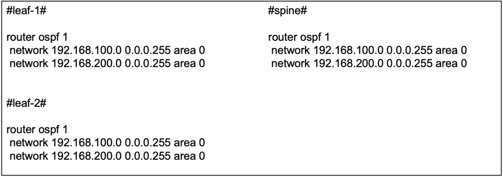
The OSPF configuration can be applied at the interface level or applied using the network command globally. So long as the IP addresses at the point-to-point links and loopback are advertised into the underlay OSPF, either way goes.
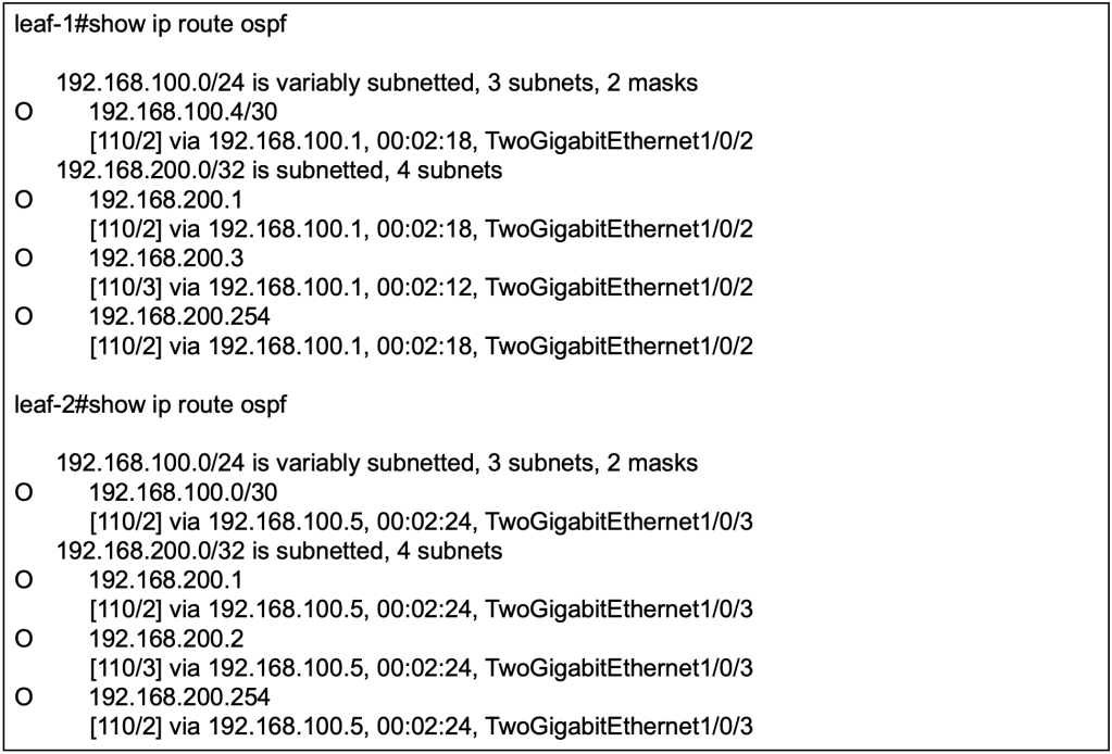
With OSPF configured and interfaces advertised, we should be able to observe that routes to loopbacks from other devices are received on the local switches. For example, to reach the loopback 0 (192.168.200.3/32) on leaf-2, the next hop for leaf-1 is the directly connected interface (192.168.100.1/30) on the spine.
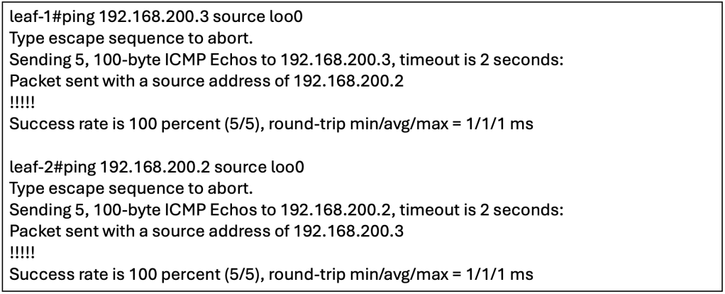
To confirm that the underlay has full reachability, we can perform ICMP reachability tests between the loopbacks. For additional tests, we can check if the Loopback 0 and 1 on the spine are reachable from the leaf(s).
Underlay Multicast
MP-BGP EVPN VXLAN handles Broadcast, Unknown Unicast and Multicast (BUM) traffic by intercepting them at the local VTEP and transmitting them to other VTEP(s) using multicast on the underlay. Alternatively, without using multicast on the underlay, there is an alternate option to use ingress replication. However, to simulate a scalable environment, we should choose to setup multicast on the underlay instead.

To explain briefly, one or more VXLAN identifier (VNI) will be mapped to an underlay multicast destination group. BUM traffic sent towards any VNI will be intercepted by the local VTEP and sent out as multicast on the underlay to the associated multicast destination group. VTEPs will participate in the associated multicast destination group based on its configured VNIs. BUM traffic for a specific VNI sent by one VTEP to the multicast destination group will be received by all other VTEPs that have been configured with the same specific VNI.
In the underlay multicast configuration, Protocol Independent Multicast (PIM) sparse mode will be used, hence we will need to allocate a Rendezvous Point (RP). Based on best practices, the RP is typically placed on the spine switch.

We have enabled PIM sparse-mode on the underlay L3 interfaces, including the NVE loopbacks (E.G loopback 0). All the switches, including the spine will point the RP towards the spine.
At this point, we have simply configured PIM and RP for multicast on the underlay. To be clear, this is just vanilla multicast. We have not yet associate BUM traffic on the overlay to be sent via underlay Multicast, but we will get to that soon.
Interior BGP
To recap, MP-BGP EVPN is the control plane for VXLAN, otherwise VXLAN will have to resort to flood and learn for MAC/IP learning across the leaf switches. Hence, we will need to setup the interior BGP (iBGP) relationship between the leaf(s) and spine, with the spine as the route reflector.

The spine will have an iBGP neighbor-ship with both leaf(s) but there is no need for a full-mesh iBGP relationship as the spine will be serving as the BGP Route Reflector (RR). Apart from forming the neighbor-ship, we will also be activating the EVPN address family inside the MP-BGP configuration. This will allow iBGP to carry EVPN information along with its BGP updates to its neighbors.
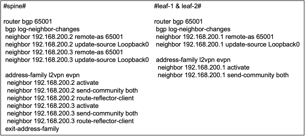
We only require iBGP in this network to carry EVPN information in its updates, to serve as the control plane for VXLAN. Hence we do not need to advertise any IPv4 unicast routes (yet) since the underlay OSPF is already doing the job of establishing reachability between the switches. We will explore further on the BGP configuration in other articles when we have the fabric to interface with external world using eBGP.
We will be using the Loopback 0 on spine and leafs(s) for the iBGP neighbor-ship. This is inline with BGP configuration best practices.
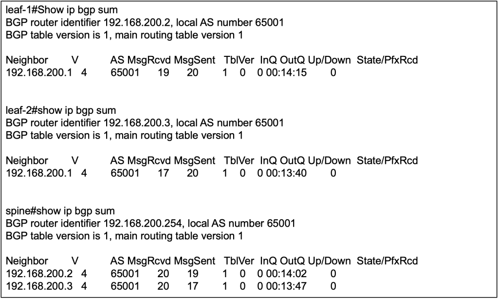
We can validate the BGP configuration first by verifying that the nieghbor-ship is up between spine and leaf(s), but not between leaf to leaf.

We will not be able to verify if the BGP address-family configuration is correct because there are no learnt EVPN routes yet. We also will not see any IPv4 routes because we explicitly did not configure any network commands to advertise the IPv4 routes.
Taking the Second Baby Steps
Now that we have configured the underlay in the previous sections, we will start with the VXLAN and EVPN configuration to support L2 overlay across a L3 network. In short, we will need to configure a L2 2 VNI service between the 2 leaf switches to allow L2 communication between host A and host B over the L3 underlay network.

In terms of configuration, most of them has already been done in setting up the underlay and the BGP. The technologies applied such as OSPF, BGP and multicast are independent on its own but here we are putting them all together to support the inner workings of MP-BGP EVPN VXLAN. Let’s begin.
Enable Global EVPN Instance
Globally, we need to enable the L2 EVPN service on the leaf switches by defining the configuration below. The configuration “replication-type static” is referring to using underlay multicast for handling BUM traffic in the fabric.

Next, we will need to define an L2 EVPN instance by running the following command and assigning the instance with an ID. In subsequent sections, we will need to assign this specific L2 EVPN instance to a specific VNI.

VLAN to VNI to EVPN Instance Mapping
As the VNI itself is simply a 24 bit segment within the VXLAN header, the number can represent either L2 or L3 VNI. In the previous section, we have already defined an L2 EVPN instance. We will need to map the VNI to the L2 EVPN instance, to create a L2 VNI. In our current context of enabling L2 overlay across a L3 network, we will need to configure both ends of the VTEPs to align a specific L2 VNI to create a L2 overlay service. Next, we will need to define a VLAN locally on the switch to associate to the EVPN instance and the VNI. Endpoints that are part of this VLAN locally on the switch will be able to access the L2 overlay service.

At this point, we have logically mapped a specific VLAN to an EVPN instance, transforming VNI 30001 to represent a L2 overlay service. What’s next will be to create an interface, Network Virtualization Edge (NVE) will logically represent the VTEP to perform encapsulation and decapsulation of VXLAN traffic.
Network Virtualization Edge
The Network Virtualization Edge (NVE) is what makes a switch become a VXLAN Tunnel Endpoint (VTEP). In the configuration we will teach the NVE to use MP-BGP EVPN as the control plane for host reachability and to define an underlay multicast group to handle BUM traffic for a specific VNI. As the NVE is a logical interface on the switch, it will rely on a loopback for an IP address.

Both VTEPs will have the same configuration as these are the generic configuration to enable an L2 overlay service. Potentially they could use different loopback address with different IP address but as long as these addresses are advertised on the underlay, its all good. The multicast group mapped to the VNI should be the same, otherwise BUM traffic sent from one VNI will not reach other leaf switches that carry the same specific VNI.
Let’s Jump In!
Before we begin to test, we might stop to wonder why have we not configured the default gateway for the subnet 10.10.10.0/24 which the test hosts will be put on? If we recall the objective of this article, it is to create an L2 overlay service using as little configuration as possible. For communication within the subnet, traffic should not require a default gateway. While in modern networks, it is unlikely that a subnet can exist without a gateway due to external communication needs. However, for the purposes of learning we will be proceeding without one.

We will attach our 1st endpoint, Host A, to the fabric via leaf 1, and our 2nd endpoint, Host B, to the fabric via leaf 2. Without further ado, let’s initiate a ping from Host A to Host B, from 10.10.10.2/24 to 10.10.10.3/24. Since both IP address belong to the same subnet, we do not need to configure a default gateway on both leaf 1 and leaf 2 as traffic will be switched instead of being routed.

We can start by configuring the IPv4 address, subnet and default gateway on our Host A. As this is a windows machine, we need to provide a default gateway even though we does not have the gateway configured yet on our switches. For Host B, we configured the IPv4 address with 10.10.10.2 and use the same for the other parameters.
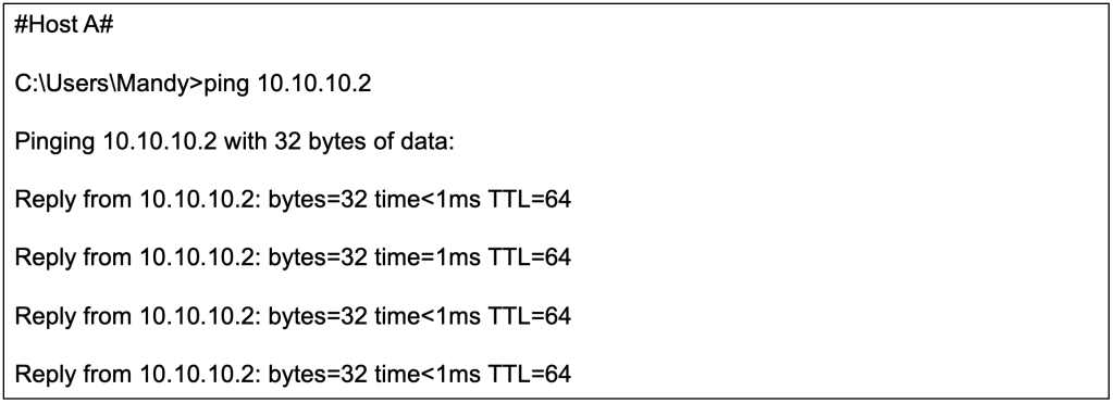
The ICMP reachability test from Host A (10.10.10.2/24) to Host B (10.10.10.3/24) is successful even though they are connected to different switches over a L3 network.
Now that we have successfully configured a L2 overlay over a L3 network, lets dissect a few moving parts under the hood.
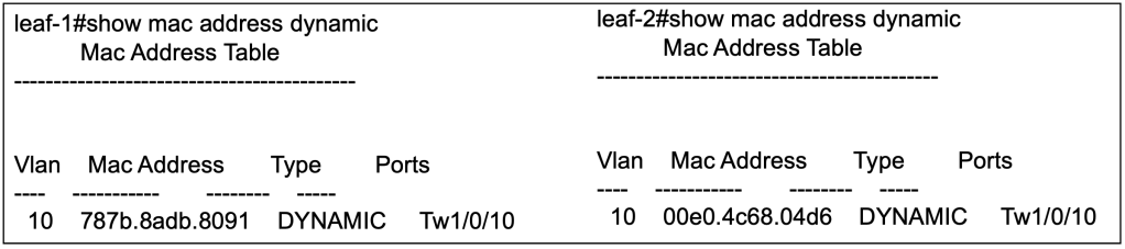
Verify Local MAC Learning
After sending out some traffic from Host A and Host B, the local switches will be able to populate its MAC address table to identify which local interface its connected to.
Verify Remote MAC Learning
We will not be able to find the MAC address of host connected to the remote leaf via the previous command. We need to use another command to verify that the local switch has learnt the MAC address of the other host, and which leaf it is connected to.

The above command has been modified so as to show only the relevant part of the output. From the outputs from respective leaf switches, we can observe that it has learnt that the remote host can be reached via the VTEP of the remote leaf switch.
There are other commands that we can use to verify that the MAC address of remote Host are learnt by the local switches. For example, we can use the following command to verify the L2 RIB.
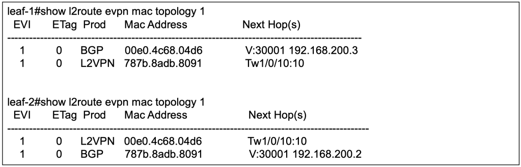
Verify MP-BGP EVPN Learnings
The information from previous section is what has been installed into the switch. However, the information regarding the remote host will come from the control plane. Over here, we will look into the outputs of MP-BGP EVPN control plane to observe the MAC address learnings.

On leaf 1, Host A with MAC address 787B.8ADB.8091 is learnt locally hence there is no next hop for the BGP. Host B with MAC address 00E0.4C68.04D6 is learnt remotely via MP-BGP EVPN with the next hop of leaf 2.
Note that there are 2 entries for each MAC address. For EVPN, the mandatory field is MAC address with IP address as optional field. The first EVPN update will be for MAC address only. With ARP, the local switch will learn the IP address of the host, hence the subsequent EVPN update will include both MAC and IP address.

Similarly on leaf 2, Host B with MAC address 00E0.4C68.04D6 is learnt locally hence there is no next hop for the BGP. Host A with MAC address 787B.8ADB.8091 is learnt remotely via MP-BGP EVPN with the next hop of leaf 1.
Closing Thoughts
We have established L2 overlay over L3 network using MP-BGP EVPN VXLAN, and tested with intra-subnet unicast. We have also verified the MAC learnings using local MAC table, and MP-BGP EVPN outputs.
At this stage, we have got some L2 traffic going between Host A and Host B over an L3 network. There are much more to verify such as to dig into how the underlay multicast is supporting the BUM traffic (E.G ARP), how ARP suppression is kicking in and to verify on the wire that packets are indeed VXLAN encapsulation with the correct VNI between the switches. Like what we have first started out, learning should be incremental and be palatable. We will leave those for the next section.
Credits to Dmytro Vishchuk for providing great references on BRKENS-3840
I got to get to office too, so see you next time.
Tang Sing Yuen, Cisco Solutions Engineer

Leave a comment